
Tolerances in FDM 3D printing: designing fits and holes that work
A correct fit comes from play, orientation and measured tests. Here's how to design holes, pins, and moving parts without relying on a universal dimension.
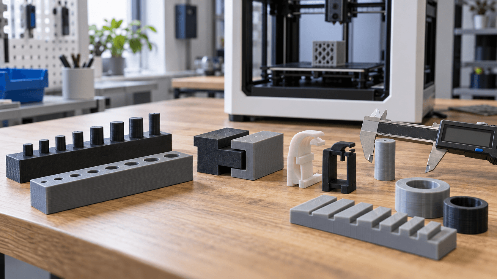
Because two equal dimensions in the CAD may not fit
In the digital model, a 10 mm pin and a 10 mm hole share the same dimension. In the real part, however, a fit without backlash hardly works. FDM printing transforms the model into layers of molten material; line width, layer height, cooling, orientation and machine dynamics introduce variations. Material, geometry and position on the print bed can also change the result. Tolerance is not a random correction added at the end. It is the acceptable size range for a feature. The clearance is instead the expected distance between two coupled surfaces. Designing well means establishing what the joint must do, leaving consistent margin and verifying the actual process. A tighter dimension is not automatically better: if it does not serve the function, it can increase rework, waste and time.
Start from the type of coupling
Before changing a diameter, define the required behavior. A loose fit allows movement or assembly without force. It is suitable, for example, for a removable lid, a guide or a pin that must rotate. A transition fit limits play and requires light pressure. An interference fit locks parts together through deformation and friction, but can damage a brittle wall or separate layers. These categories do not correspond to a single value that applies to all printers. The Prusa guide reminds you that optimal tolerance depends on size, orientation, geometry, calibration, settings and material. Formlabs also describes the fit as continuous: more freedom of movement means more play, while a tight fit increases friction, wear and assembly force. The function therefore comes before the number. For each interface, write down four pieces of information: it must move or remain still; must be removable; what load it receives; which surface is critical. This simple record avoids applying the same compensation to holes, clips, guides and hinges with different needs.
Holes and Pins: Measure actual geometry
FDM holes may be smaller than nominal. Polygonal contour, extruder trajectory, inwardly deposited material, and crushed first layer contribute to the error. A horizontal hole adds bridges and cantilevers; a vertical one is built with overlapping perimeters and can have different behavior. Even a post can grow or shrink unevenly. Do not offset all holes the same increment before measuring. Print a specimen with multiple diameters around the expected dimension, in the same material, orientation and profile of the component. Let it cool, then measure in multiple directions with an appropriate tool. A caliper is useful for many practical checks, but it does not demonstrate circularity or internal shape on its own; for strict requirements, specific gauges, dial indicators or metrological methods may be needed. If a hole is to receive a screw, also clarify whether it will be through, tapped, reamed, or used with an insert. The CAD dimension and control change. For single pieces, subsequent machining can be efficient. For a series, it is better to qualify geometry and process to reduce non-repeatable manual interventions.
Orientation, first layer and load direction
Orientation influences both measurement and resistance. A circular feature printed on the Z axis does not reproduce the same conditions as one printed sideways. The surfaces resting on the supports may be rougher; a face on the print bed can widen in the first layer. If the joint works close to the base, the so-called elephant foot can prevent assembly even when the rest of the dimension is correct. Compensation of the first layer available in the slicer can help, but it should not hide a poorly adjusted print bed or excessive crushing. Prusa reports that values that are too high can also distort fine details connected to larger areas. Check calibration first, then apply limited, controlled compensation. Also consider the load. A clip that flexes between layers can delaminate before reaching its intended travel. A strong fit in the XY direction may be weak along Z. Orient the specimen and component as they will be produced; a test rotated ninety degrees may provide a non-transferable result.
Create a useful test coupon, not a collection of numbers
A good coupon reproduces the functional area. For a pin and hole it includes diameters close to the nominal dimension; for a guide use the same contact length; for a clip it preserves thickness, radius and bending direction. Place identifiers outside of active surfaces, without details so small they become unreadable. Change the clearance in regular steps and record for each sample material, machine, nozzle, layer height, orientation, position on the table and profile. Evaluate with explicit criteria: enters by hand, slides without blocking, does not oscillate beyond the limit, resists a defined number of cycles. “It seems right” is not enough when the data needs to be reused. Repeat the sample at least at different times before settling on an internal rule. A single print describes an example, not the variability of the process. If the spool, material, nozzle, or orientation changes, recheck the critical features. A compensation table is only valid for the conditions in which it was constructed.
Correct in CAD or slicer
A change in CAD makes the design intent explicit and follows the file when it is produced elsewhere. It is the preferable choice for component-specific clearances, seats and fits. Slicer XY compensations can be useful for systematic machine drift, but they act on multiple geometries and can improve a hole while worsening a wall or pin. Avoid adding undocumented corrections in CAD, slicer and post-processing. If the piece works, it must be clear why. Keep revised model, profile and test result. For a critical part, also define measurement method and acceptance criteria before starting the batch.
From the first fit to small-batch production
Effective tolerance arises from the connection between function, project and process. Define the fit type, orient the part realistically, print a representative coupon, measure after cooling and validate the complete component. Only then do you transfer the result to production. Do you have an assembly that doesn't fit or a hole that changes between prototypes? [Contact ADIVO](https://adivo.it/en/contatti) with CAD, material, quantity and function of the coupling: we can prepare a specimen, measure the critical dimensions and validate the design before the small series.