
Inter-layer adhesion in FDM 3D printing: avoid cracks and delamination
Sharp cracks and separating layers indicate a process that needs to be corrected. Learn how to distinguish delamination, underextrusion and load failure.
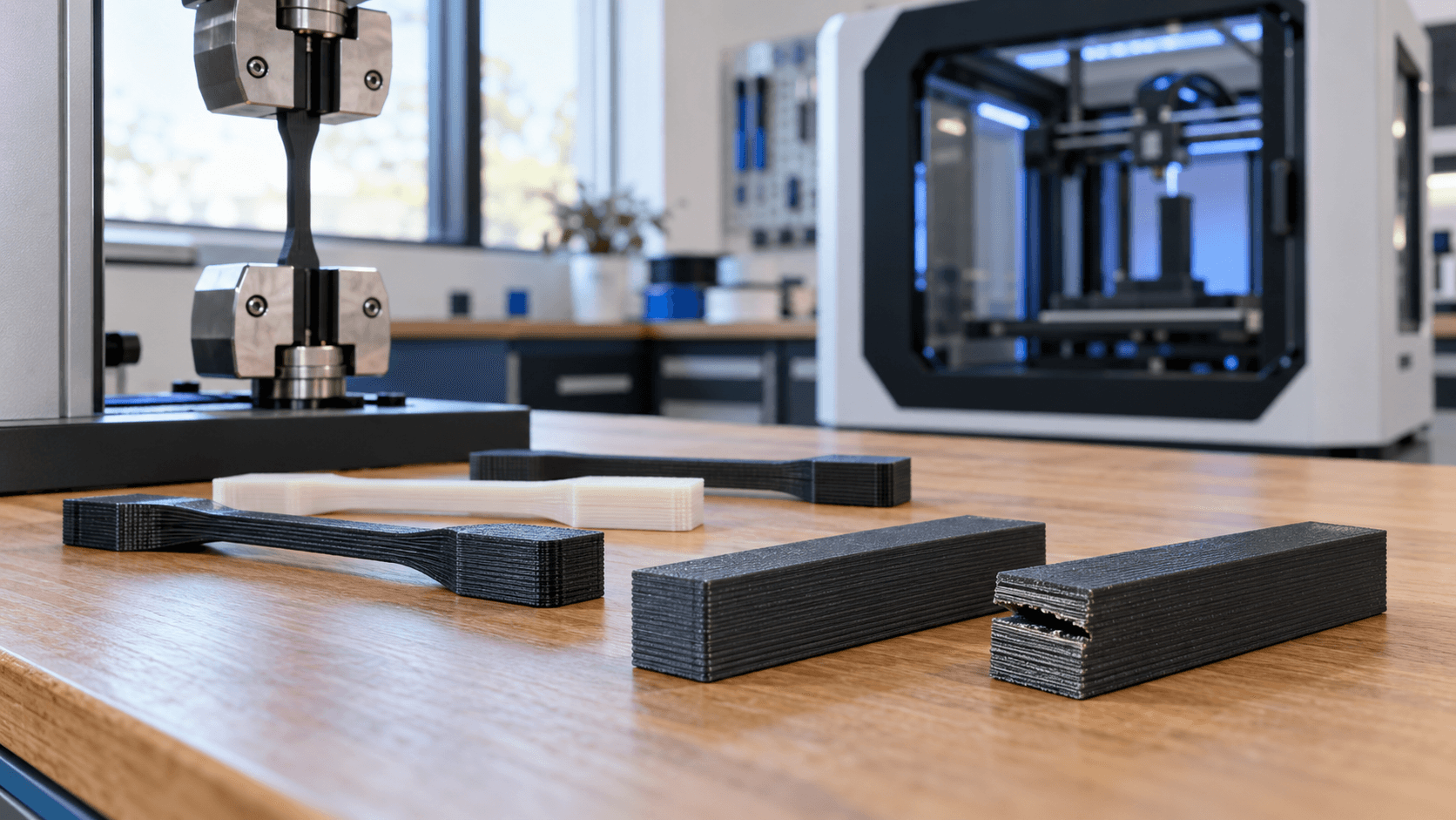
What does inter-layer adhesion mean
In FDM printing, each line of hot polymer is deposited on top of already extruded material. The new strand must wet the underlying surface and create sufficient bonding as the polymer chains diffuse to the interface. When temperature, contact time and pressure are not adequate, gaps or weak joints remain between the lines. The part may appear correct, but open along a layer under load. Production by layers also makes the component anisotropic: the mechanical response changes with the direction. A load parallel to the deposited lines does not cross the same interfaces as a load along the Z axis. NIST describes just how deformation, molecular orientation, and thermal history of deposition affect bonding between extrudates and final properties. For this reason "strong material" does not automatically mean "strong part in every direction".
Delamination, missing layer or load failure
The diagnosis starts from the appearance of the defect. Delamination often creates a fairly sharp crack along the plane of the layers. It can appear during printing, during cooling or when the component is stressed. A slightly upward-curving crack suggests shrinkage stresses: the layers cool at different rates and the internal force overcomes the bond between them. A missing layer instead has absent or discontinuous material. The cause may be underextrusion, partially clogged nozzle, dirty gears, poorly flowing filament or incompatible profile. The Prusa guide distinguishes extrusion voids from clean cracks and reminds that an underextruded part tends to be brittle. An irregular fracture occurring only above a known load may ultimately be the normal limit of the component, not a process defect. Observe where the break originates, photograph the section and compare multiple samples. If the crack always appears at the same height, check for process events there: speed change, pause, draft, or feed irregularity. If it appears in random positions, check the extrusion and material first.
Temperature and material profile
A nozzle temperature that is too low can deposit a line that solidifies before bonding well to the previous one. Increasing it indiscriminately is not the solution: excessive values can degrade the material, worsen details, generate stringing or exceed the limits indicated by the manufacturer. Start from an official preset compatible with the printer, nozzle and filament, then perform a small test within the range of the data sheet. Prusa suggests gradual increments when the PLA shows separation, but the number is not universal. The actual temperature depends on the sensor, hotend, flow rate and speed. Edit one variable at a time and also evaluate surface finish, bridges, overhangs and dimensional stability. A temperature tower can guide the choice, but the final test must use component geometry and orientation. Speed and flow rate are also linked. Increasing speed without sufficient melting capacity can reduce the effective temperature of the deposited material. Too low a flow leaves spaces between perimeters and layers; one that is too high alters heights and surfaces. Before changing the extrusion multiplier, check filament diameter, nozzle, gears and feed path.
Cooling and printing environment
The fan helps details and bridges, but excessive cooling reduces the time needed for bonding between layers. External air currents and changes in ambient temperature can create the same problem, especially on large parts or materials subject to shrinkage. ABS and ASA often require a more stable environment than many PLAs and PETGs; always follow the manufacturer's instructions and machine profile. A closed chamber does not permit improvised temperatures. Electronics, filament and printer have specific limitations; some machines are not designed to work in a hot enclosure. Do not cover or modify the printer without the manufacturer's instructions. For materials that may emit particles or volatile compounds, manage ventilation and exposure according to safety data sheets and workplace assessments. Experimental research on technical polymers confirms the role of thermal history: studies on PEI have observed better adhesion and fewer voids with controlled heating during the process. These results don't translate directly to PLA or PETG, but they show why interface temperature and uniform cooling matter.
Orientation and geometry of the component
If the load opens the layers like the pages of a book, the joint works in the most critical direction. Rotating the workpiece can bring the main lines along the path of the load and reduce the normal stress at the interfaces. However, the choice must consider supports, precision, finish and time: there is no best orientation for all functions. Geometry also concentrates stresses. Sharp edges, abrupt changes in section, holes close to the edge and very thin walls can initiate a crack. Radius, fillets and progressive transitions distribute the load. Increasing the infill alone does not necessarily correct a weak exterior wall or poorly oriented seam; Often multiple perimeters and load paths count.
A test procedure without random fixes
1. Reset correct preset for machine, nozzle and material. 2. Check spool, filament path, gears and possible obstruction. 3. Print two identical specimens in the actual orientation of the part. 4. Only vary the temperature, remaining within the manufacturer's limits. 5. If needed, test cooling and speed in separate steps. 6. Record profile, lot, orientation, mass, and failure mode. Comparing only the maximum load can be misleading. Note whether the break passes through the material or follows a layer, whether the sample deforms, and whether the defect is repeatable. For functional or series parts, use specimens and test methods consistent with the requirement and material; a manual test does not replace an engineering validation.
From visible defect to stable process
Layer adhesion depends on the entire system: material, temperature, flow rate, cooling, environment, orientation and geometry. Fixing everything together hides the cause. A controlled sequence instead allows you to separate underextrusion, thermal stresses and unfavorable design, reducing reprints and false improvements. Is your component cracking along layers or breaking sooner than expected? [Contact ADIVO](https://adivo.it/en/contatti) with 3D file, material, profile and photo of the fracture: we can evaluate orientation, parameters and a test plan before production.